“One of the greatest challenges in this world is to know enough about a subject to think you’re right but not enough about a subject to know you’re wrong.”
-Neil deGrasse Tyson
I was born in Los Angeles, CA, but I now call the beautiful Knoxville, TN home. I am the third child out of four, but I have always considered myself the middle child. I enjoy juggling, cooking, and have recently discovered FPV drone racing. Check out my Additional Interests page to learn more!
Education
Vanderbilt University Class of 2024 Major: Mechanical Engineering Minor: Computer Science
Career
I hope to pursue a career in software for applications in cyber physical systems, robotics, or autonomous vehicles.
Experience
Nov 2020 - Jan 2021
Kitchen Staff
Kung Fu Tea
Knoxville, TN
May 2021 - Aug 2021
Licensing Intern
Vanderbilt Center for Technology Transfer & Commercialization
Nashville, TN
Feb 2022 - Aug 2022
Undergraduate Researcher
Robotics and Autonomous Systems Lab
Nashville, TN
Dec 2022 - May 2023
Research Assistant
Institute for Software Integrated Systems
Nashville, TN
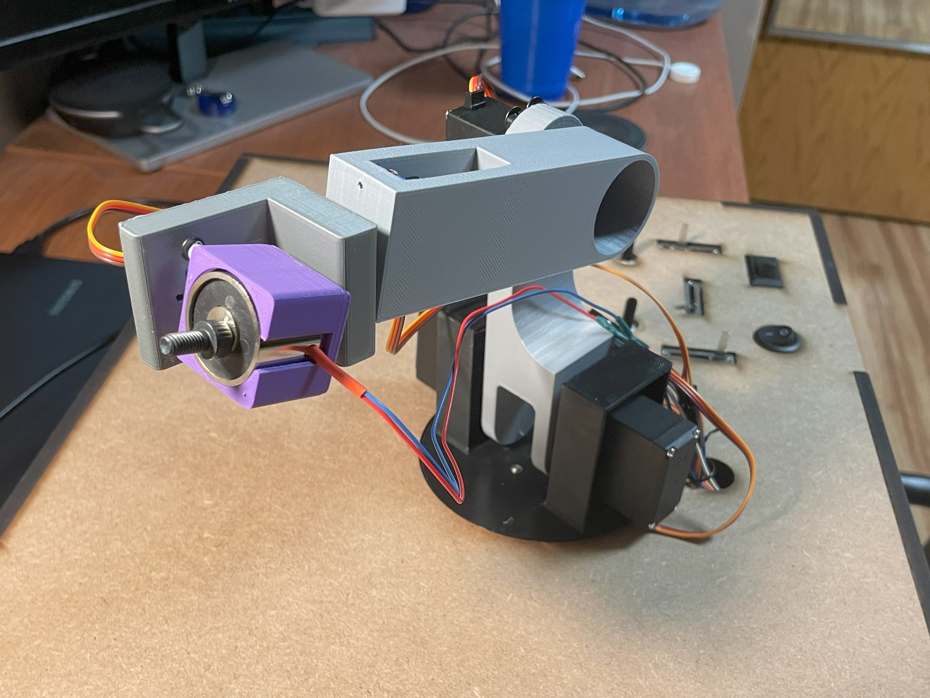
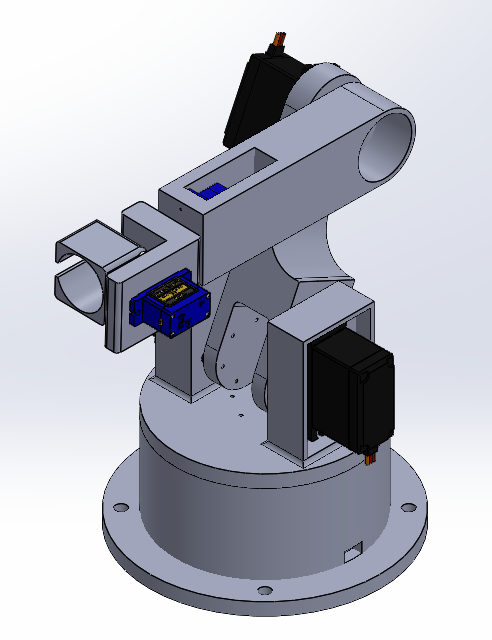
Depicted above is the 5 degree of freedom robotic arm I designed and built. An electromagnet serves as the end effector and the motion of the robotic arm is dictated by 3 linear potentiometers, where each potentiometer represents the electromagnet’s three-dimensional Cartesian coordinates. Inverse kinematics is used to determine the joint angles to achieve specified spatial coordinates. Additionally, rotary potentiometers and switches are used to adjust the orientation of the electromagnet and turn the robotic arm and electromagnet on and off, respectively. The complete arm is stored in a self-designed box to create a clean user interface and protect the electrical components and user from each other.
The construction of the inverse kinematic arm can be split into three categories: hardware, electrical, and software.
Hardware: The main body of the robotic arm was designed using CAD and 3D printing. The links of the arm are attached and actuated with 180ᵒ servos to allow for 5 degrees of freedom. A total of 6 servos are used to actuate the arm with all servos being controlled by a servo shield attached to an Arduino Uno.
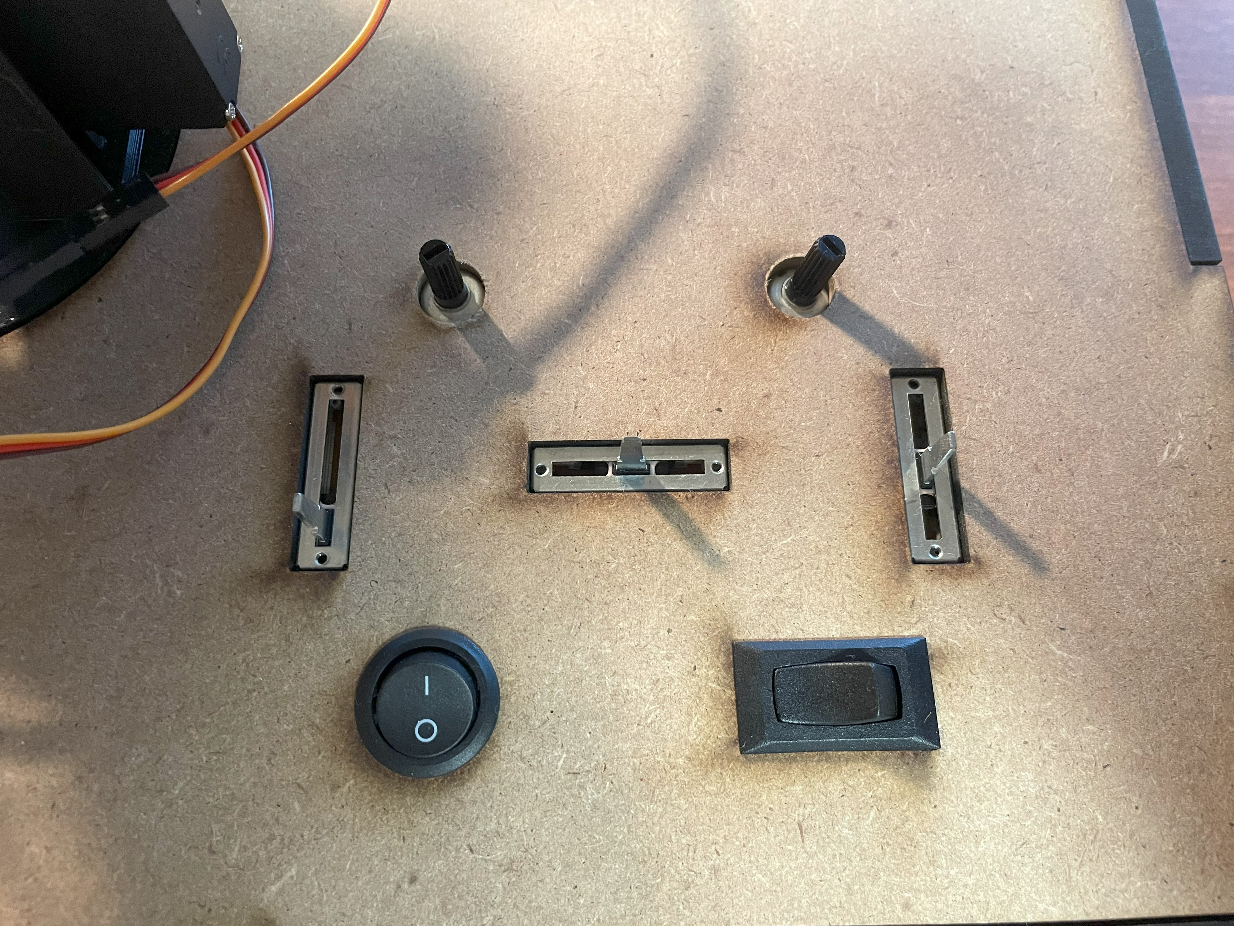
To operate the arm, 5 potentiometers (3 linear, 2 rotary) and 2 switches are used. The three linear potentiometers control the x, y, and z Cartesian coordinates of the end effector and the 2 rotary potentiometers control the rotation (roll, pitch) of the end effector. 2 switches are used to turn the robotic arm and electromagnet arm on and off, respectively.
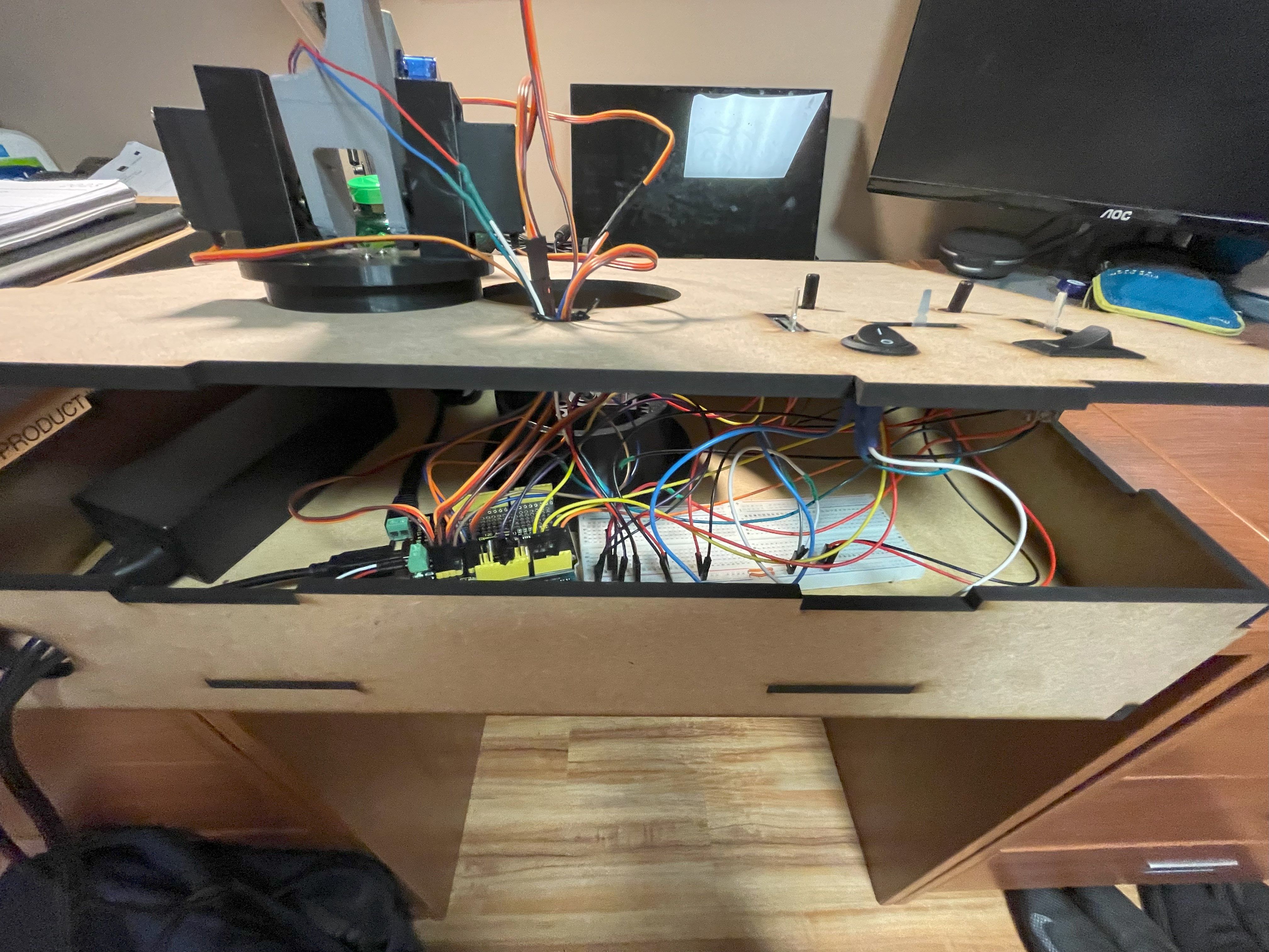
Electrical: The 4 larger servos on the arm operate at 5 volts and 3 amperes, the 2 micro-servos operate at 5 volts and 1 ampere, and the electromagnet operates at 5 volts and < 1 ampere . Thus, to accommodate such power requirements, a 5V and 15A power supply was chosen. The power supply powers the servo shield using a barrel jack adaptor with screw terminals while the Arduino Uno is powered by a laptop. The servos plug directly into the servo pins on the servo shield and are controlled with PWM on an I2C communication protocol. The potentiometers plug into the analog pins on the servo shield and the switches plug into the digital pins on the servo shield.
Software: All software was developed using the Arduino C++ variant language with the Adafruit PWM Servo Driver library. The inverse kinematic math used to determine joint angles required the implementation of the law of cosines in helper functions, while the functions used to drive the servo motors were provided by the Adafruit library. The Adafruit driver library controls servos by specifying the start and end time of a PWM output within a 4096-part cycle. However, to make the inverse kinematic algorithm clearer, a helper function was made that converts an angle in degrees to the appropriate input value for the Adafruit library driver function.
While the implementation of inverse kinematics in code didn’t require much more than utilizing the law of cosines, figuring out the bounds of the end effector’s position proved to be the challenge. To determine the allowable x, y, and z values of the robotic arm, the length of the arm’s links and the restricted range of motion of the servos (180ᵒ) all needed to be considered, increasing the complexity of the inverse kinematic solutions. Ultimately, I used an iterative approach in Excel to figure out the bounds of the robotic arm’s motion.
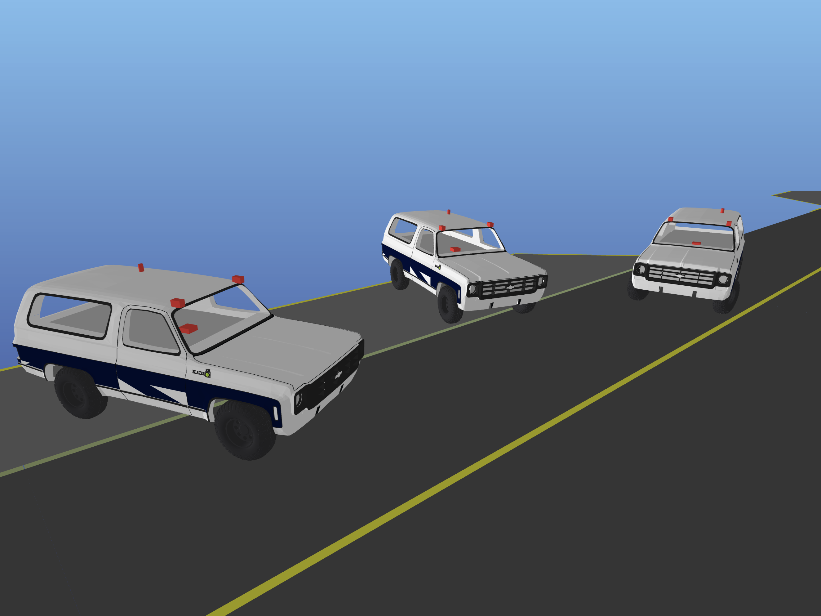
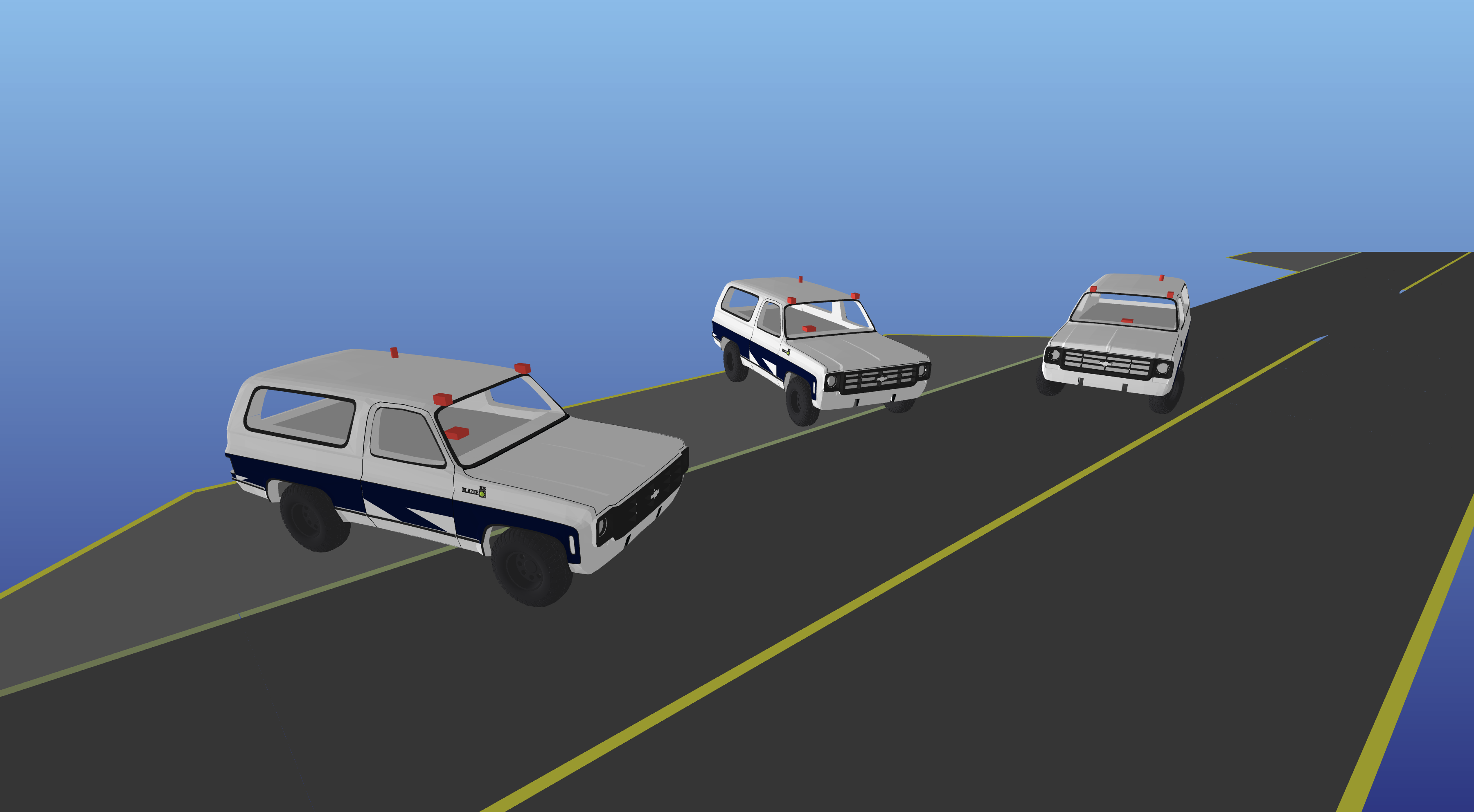
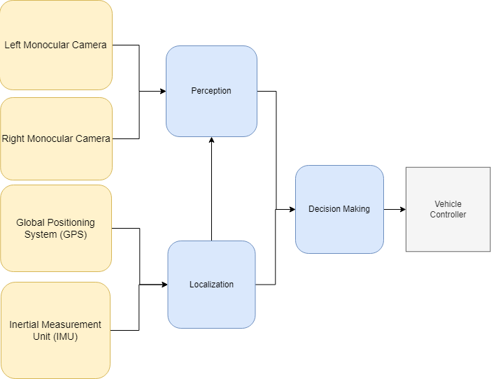
For the final project of my Autonomous Vehicles course, all students were paired up in teams to develop an autonomous vehicle for navigation in a simulated world. Using what we learned throughout the school semester about the components of an autonomous vehicle, our team split our software stack into three modules: localization, perception, and decision making. The localization module combines measurements received from a GPS and IMU to estimate the position of the ego vehicle and the perception module combines measurements received from two cameras to estimate the position of other vehicles on the road. An Extended Kalman Filter is used in both the localization and perception modules to pass accurate data to the decision making module, where vehicle control commands are computed and sent to the vehicle controller on the simulation server. A diagram of our complete autonomy stack is shown below.
I was in charge of the decision making module and tasked with safely and properly navigating our vehicle between target passenger pick-up and drop-off zones on the map. To create proper autonomous navigation, I split the decision making module into two components: route planning and motion planning.
Route Planning: When first loading into the simulation server, the ego vehicle is placed in a random position on the map and given a target loading zone ID. Thus, before any commands (velocity, steering angle) can be sent to the ego vehicle, the decision making module is first tasked with determining the starting road segment of the ego vehicle and the path required to get to the target loading zone. The road segment corresponding to the current position of the ego vehicle is determined by comparing the position data from the localization module to each road segment in the map. The map generated in the server is represented through a dictionary where the key is a road segment ID number, and the value is a RoadSegment data type, which contains information about each individual road segment such as length, position, road segment type, and adjacent roads. With the boundaries of each road segment being defined with beginning and end points of the road, each road segment can be represented as a polygon. The entire map can then be traversed to determine which polygon or road segment the current position of the ego vehicle is in. To determine if the position of our ego vehicle is in a certain road segment polygon, I employ a ray casting algorithm between a line drawn through the point of interest and the edges of a polygon.
Once the road segment position of the ego vehicle is established, I implemented Dijkstra’s algorithm to find the shortest travel distance path from the ego vehicle to the target loading zone ID. With the road segments and their respective neighbor roads being represented in the map dictionary with an adjacency list, Dijkstra’s algorithm reliably determines the sequence of road segment IDs creating the shortest path between the ego vehicle and the target loading zone. To ensure efficiency of route planning, I decided to implement Dijkstra’s algorithm with the heap data structure.
Motion Planning: Driving the ego vehicle involves calculating and sending a target velocity and steering angle to the car. To calculate the required target velocity of the vehicle for proper motion, a type of proportional controller is used, where the distance between the ego vehicle and another car or stop sign dictate the set target velocity. The closer the ego vehicle is to another car or stop sign, the lower the target velocity is set. The steering angle is also calculated using a proportional controller; however, to keep the ego vehicle within the lane boundaries of the road segment it is on, more computations first need to be done. Using a similar strategy as the solution to find which road segment the ego vehicle is on, each road segment can be split into a series of 3 polygons: one to represent the left side of the road, one to represent the right side of the road, and one to represent the middle of the road. The position of the ego vehicle can then be used to determine which side of a specific road segment the ego vehicle is on. After determining which side of the road the ego vehicle is on, the steering angle can be adjusted with the proportional controller to ensure the vehicle stays within the bounds of the road.
During Summer 2022, I was hired as an undergraduate researcher at the Vanderbilt Robotics and Autonomous Systems Lab. Over the 3 months of the internship, I worked on further developing and prototyping a haptic thermal system that would be capable of bringing thermal sensation to augmented reality.
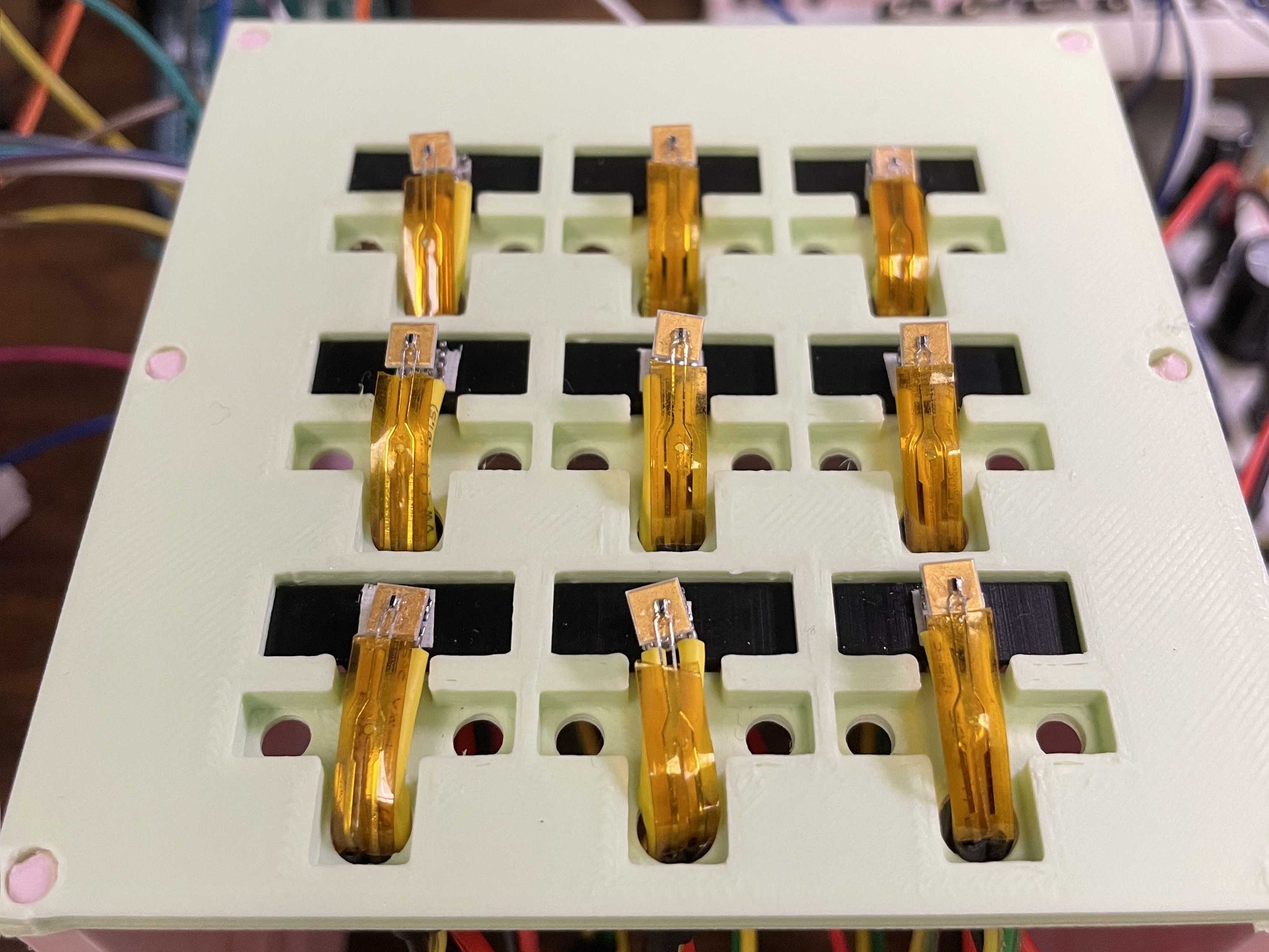
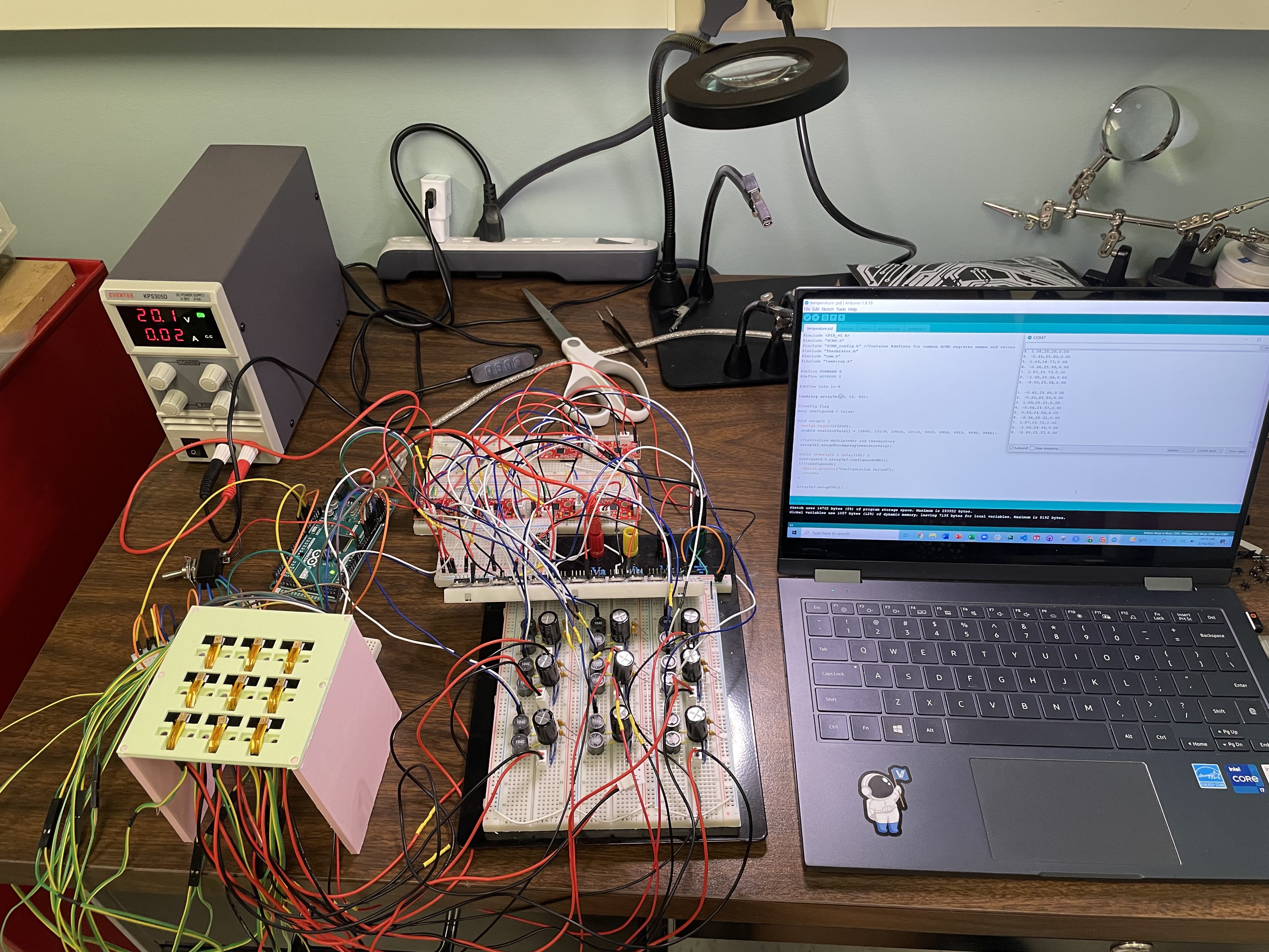
Within the first week of summer research, I read prior research and documentation on similar systems to become familiar with the science and hardware required to build such a system. With a single heat delivery device known as a thermal electric module (TEM) already created by the lab as a proof of concept, I spent the next 3 weeks crimping, soldering, 3D modeling, 3D printing, and assembling hardware to scale the single proof of concept TEM to a 3x3 array of TEM devices. In addition to prototyping a larger heat delivery system, I programmed the system’s control code, which handled heat delivery to specified input temperatures. By the end of the first month of my internship, a complete yet unreliable thermal system was created with capabilities of delivering heating or cooling to maintain TEM surface temperatures between -20 degrees Celsius and 100 degrees Celsius.
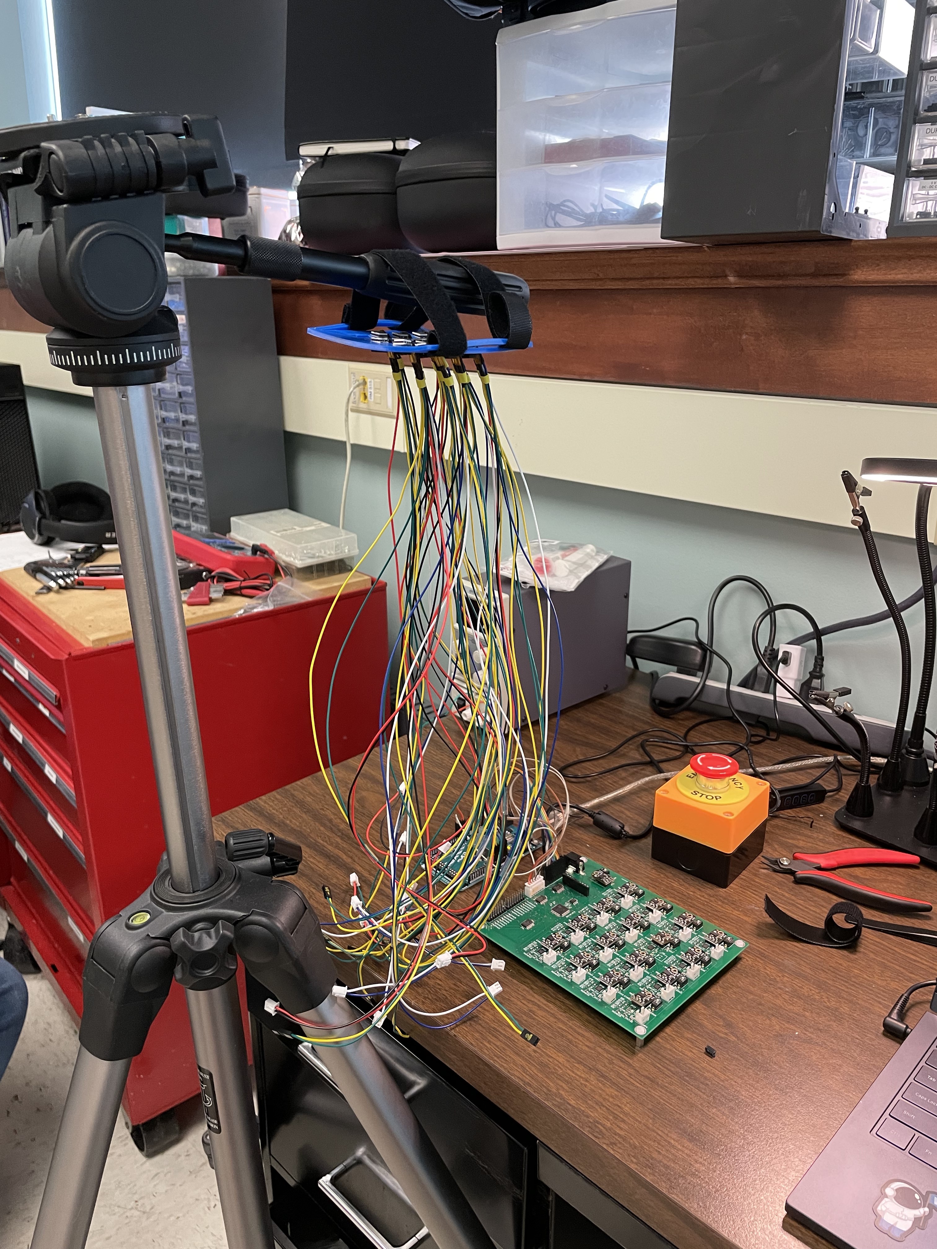
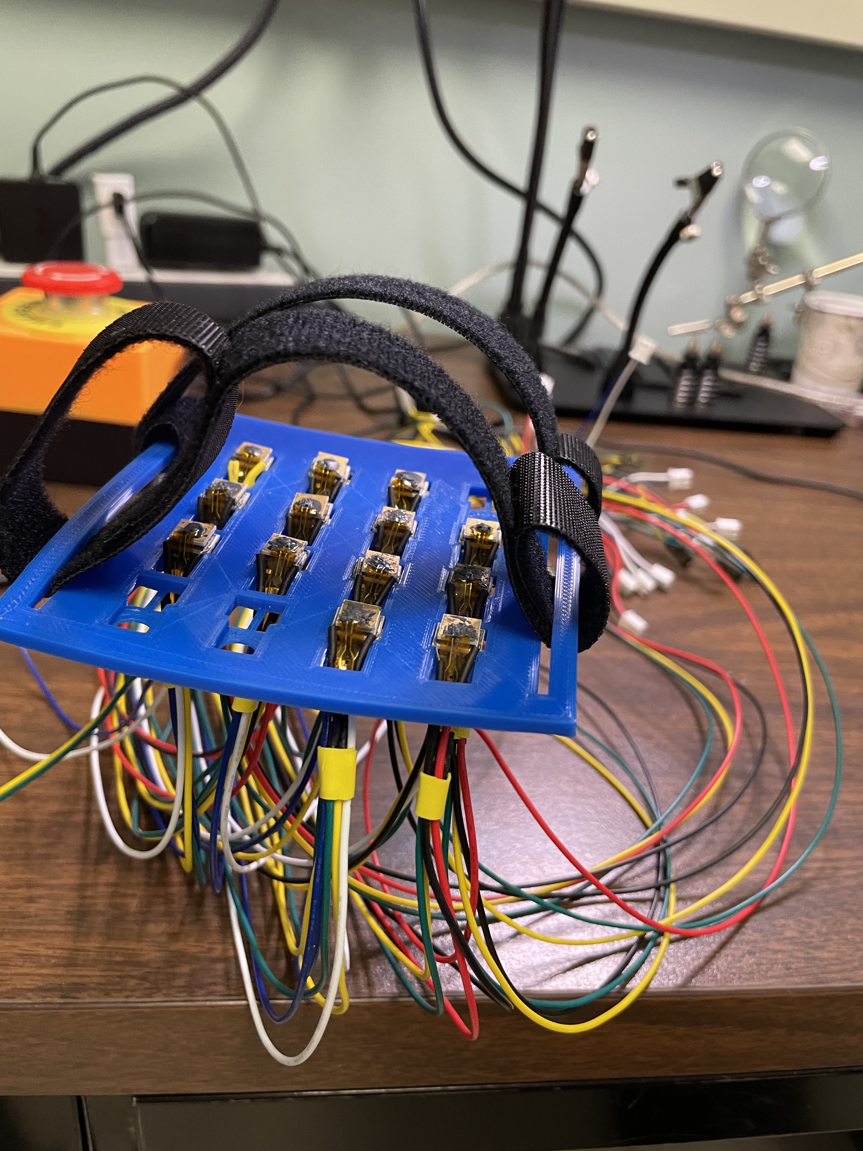
While the initial 3x3 array prototype allowed for better thermal detection and testing, the fragile circuitry on the bread board led to sporadic issues such as command signal delays that caused multiple TEM devices to overheat and melt. Because of such faults and concerns for the user’s safety, for the next month a graduate student and I started working on transitioning the thermal device to a 4x4 array controlled by a PCB. Safety hardware such as emergency shut off switches and software fail safes were also implemented. After weeks of redesigning mounts, building TEM devices, assembling hardware, and updating the control code to provide more thermal device features, a more robust 4x4 thermal array was developed.
The video below, produced from a thermal camera, shows the temperature performance of the thermal array in degrees Celcius.
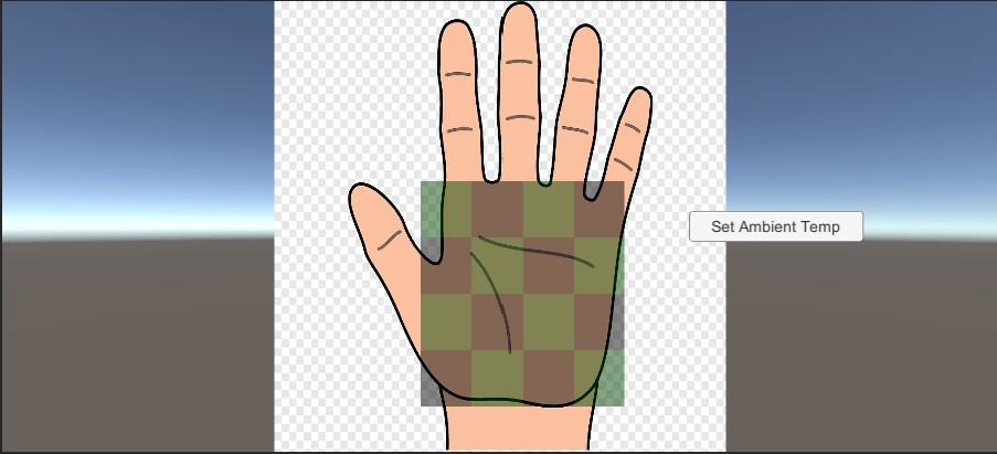
The last month of my summer research consisted of implementing the 4x4 thermal array with augmented reality. Using Unity, I developed 3 GUIs to test different capabilities of the thermal system. In the first GUI, a specified temperature is delivered to a single black or green region specified by the user.
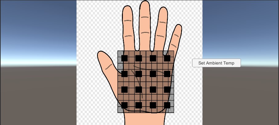
In the second GUI, the user is able to select anywhere on the 4x4 graphic, which is used to depict the individual thermal devices in the system. Wherever the user selects, a specified temperature will be concentrated at that point and radiate outwards. This allows the user to click and drag their mouse around the graphic and feel thermal sensations tracing the same path on their physical hand.
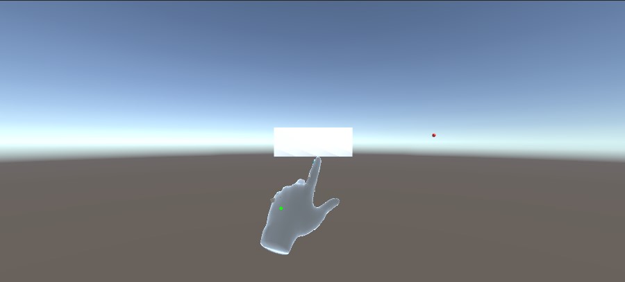
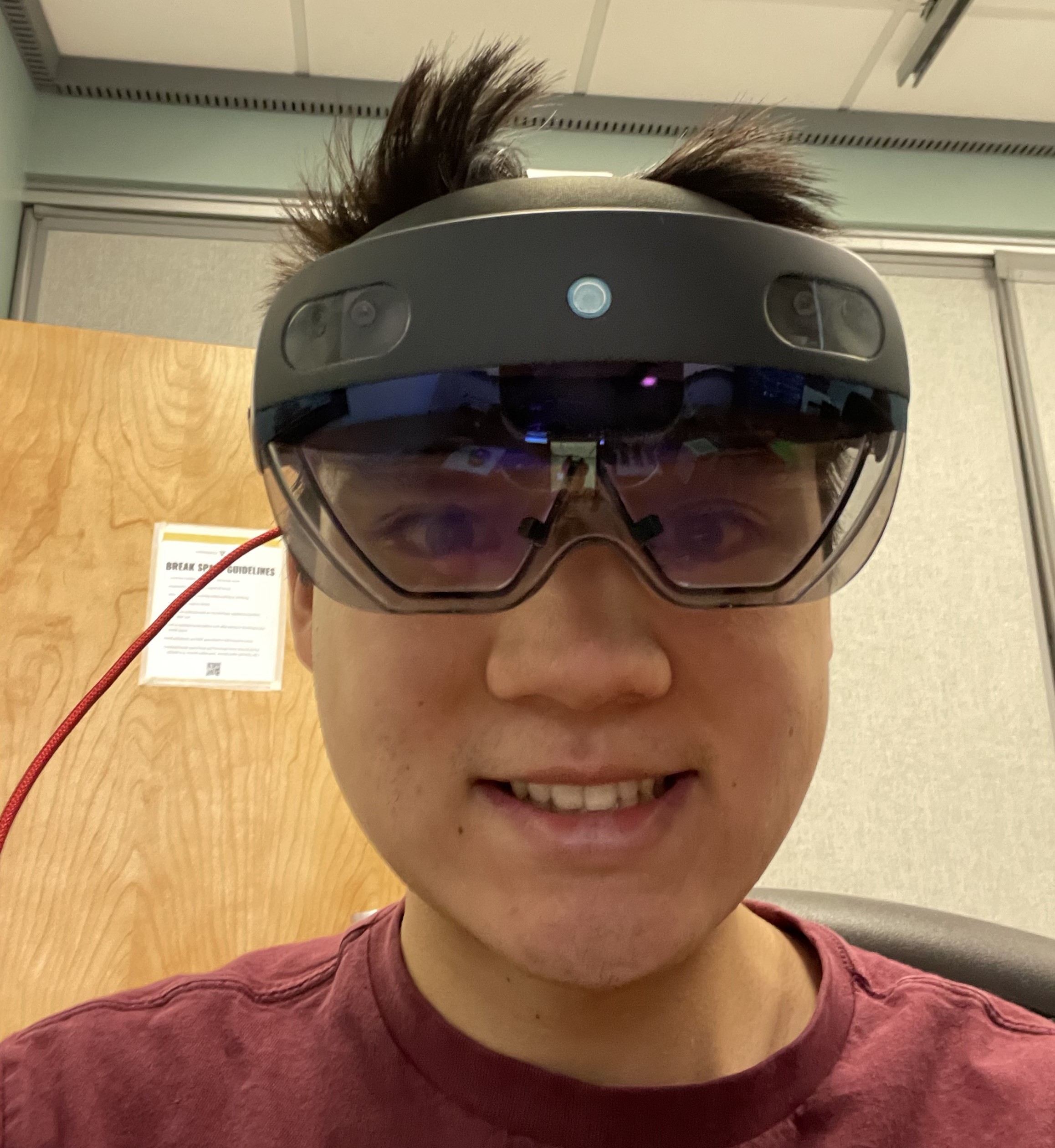
In the third GUI, the user utilizes a HoloLens2 to track their hand. When the user’s hand comes into contact with the white box, a red ball moves across the screen, indicating where a specified temperature is applied. If the user’s hand ever leaves the white box, the thermal system will shut off; however, if the user’s hand remains in contact with the white box as the red ball moves over it, then they will experience a thermal sensation across their hand.
Reflection: During my three months of summer research, I was able to learn much about control systems and gained many valuable skills with hardware assembly and firmware. However, perhaps one of the most valuable skills I learned was how to problem solve, but in a way different than homework problem sets or class assignments. Above comments on the highlights of my summer research, and while I am proud of all that I was able to create and learn during my experience, a majority of the three months were filled with rebuilding broken hardware, debugging code, and troubleshooting with a multimeter and logic analyzer. Initially when problems would arise, I would often have to ask a graduate student on what they thought went wrong. How they methodically dissected the issue to find the root cause of the problem was practical problem solving that I was unfamiliar with but eager to learn. How they asked me continuously narrowing questions to lead their investigation drew similarities from the way a medical doctor diagnoses a patient, and often succeeded. With practice and more observation, I was eventually able to troubleshoot some issues on my own. I thoroughly enjoyed this experience and look forward to pursuing future opportunities to continue learning and growing my skillset.
Date: Summer 2022
Mobile Sensory Unit
Components: Rapid Prototyping, CAD, 3D-Printing
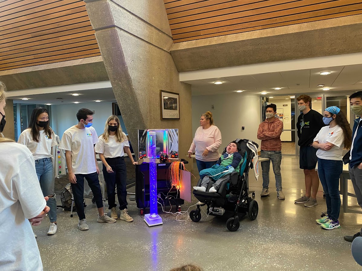
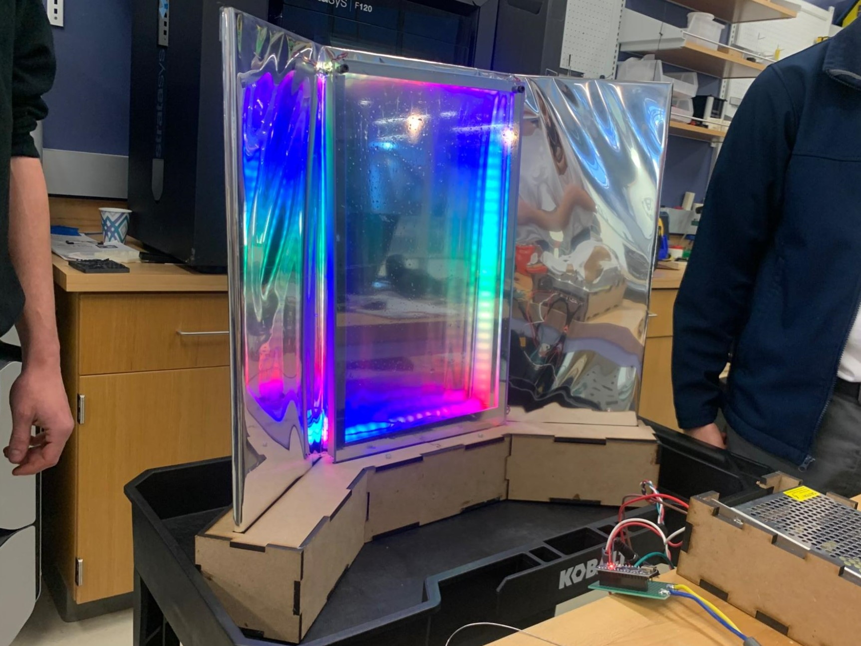
The mobile sensory unit depicted above was part of a rapid prototyping event for the Tikkun Olam Makers. In this event, a group of students and I were tasked with aiding Adam (center of image above) with his everyday need of constant sensory stimulation. As a solution, my team developed a mobile sensory unit modeled after the sensory stations found in pediatric hospitals. In addition to centralizing and organizing Adam’s preexisting sensory instruments, we developed two additional sensory devices to include on the mobile unit. The first addition was an infinity mirror display with a ring of LEDs around it and the second was a vibrating button box.
Besides improving my technical skills in 3D printing and product fabrication, working on this project gave me experience with being on a team and rapid prototyping. Because we were only given 3 days to brainstorm and develop a solution, I quickly learned the importance of communication, and collaboration.
Date: November, 2021
Personal Website
Components: HTML, CSS, Jekyll, GitHub Pages
By combining the advice I recieved to start an engineering portfolio and my desire to learn web development, I decided to create this personal website. The main tools used to create my website are Jekyll, which is a package written in Ruby that allows for static site generation, and GitHub Pages, which hosts my website. Having never had prior experience with web development, Jekyll made it easy for me to start building my website as it supports website templates online. However, as I started to build my website I quickly found myself wanting to make modifications to the template I found, but lacked the knowledge of how to do so. I found myself scouring the web to learn the basics of HTML, CSS, Bootstrap, and Liquid and eventually, I was able to create the “Additional Interests” section as well as change a majority of the template layouts and functionality.
As I continue to build my personal website, I am learning the importance of perseverance, especially when it comes to learning a new skill. From the start of learning about web development, I quickly realized the expansiveness and depth of the subject. Modifying certain HTML and CSS files for my website often took me days to fully figure out, but the long hours only made seeing the desired results even more rewarding. I am excited to continue building my website and exploring web development and look forward to sharing what I have and will learn!
Date: Summer 2022
Additional Interests
Click icons for more!
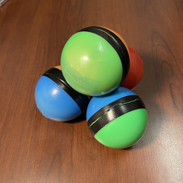
Juggling
Cooking
Juggling
Torches
Three Ball Cascade
Three Ball Reverse Cascade
Half-Box
Mills Mess
Romeo’s Revenge
Four Ball Cascade
Cooking
Shrimp Fried Rice
Mom’s famous shrimp fried rice! For as long as I can remember, the Panda Express style wok has been a staple kitchen appliance in our household. Growing up, I was fortunate enough to enjoy all types of Chinese stir fry dishes with fried rice always being a family and friend favorite. The shrimp fried rice had a nice char and smokey flavor from the high heat of the wok and the onions and carrots added a balanced sweetness. Even though a seasoned wok adds a unique depth of flavor to the dish, the secret ingredient to my mom’s fried rice is white pepper. When I cook fried rice, it is often rare that I have access to a wok, but by simply adding white pepper my fried rice is elevated and I am reminded of home. Rating: 9.5/10
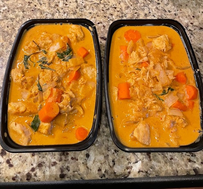
Panang Curry
After searching for easy Instant Pot dishes, I stumbled across this panang curry. Having never made panang curry I was excited to try, and this simple recipe turned out great. I decided to add carrots to the recipe and modified a couple of the ingredients, but still produced a sweet, salty, Thai spicy dish. The curry was rich in flavor, and I will definitely be making it again! Rating: 9/10
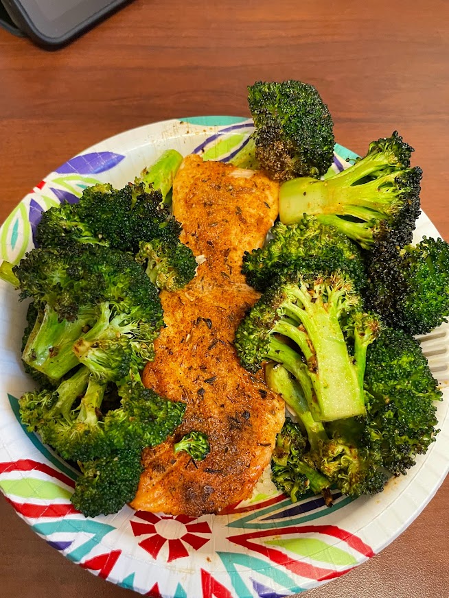
Air Fryer Salmon and Roasted Broccoli
I finally gave the craze of air fried salmon a try and it did not disappoint. The salmon was tender on the inside and flakey around the edges, which paired perfectly with the crunchy broccoli. Also, the whole meal only took 20 minutes to cook! Rating: 8.5/10
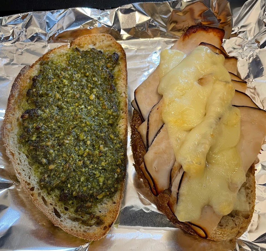
Turkey Pesto Sandwich
I discovered this glorious sandwich during my Summer 2022 internship. Needing something quick and easy to make for my lunch break, I decided to layer pesto, sliced turkey breast, and creamy gouda cheese onto toasted sour dough bread. This sandwich definitely made my lunch breaks. Rating: 8.5/10
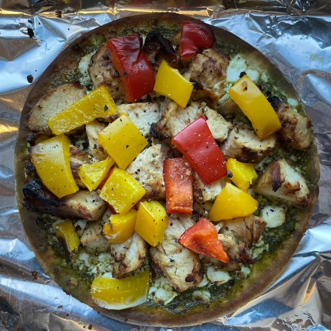
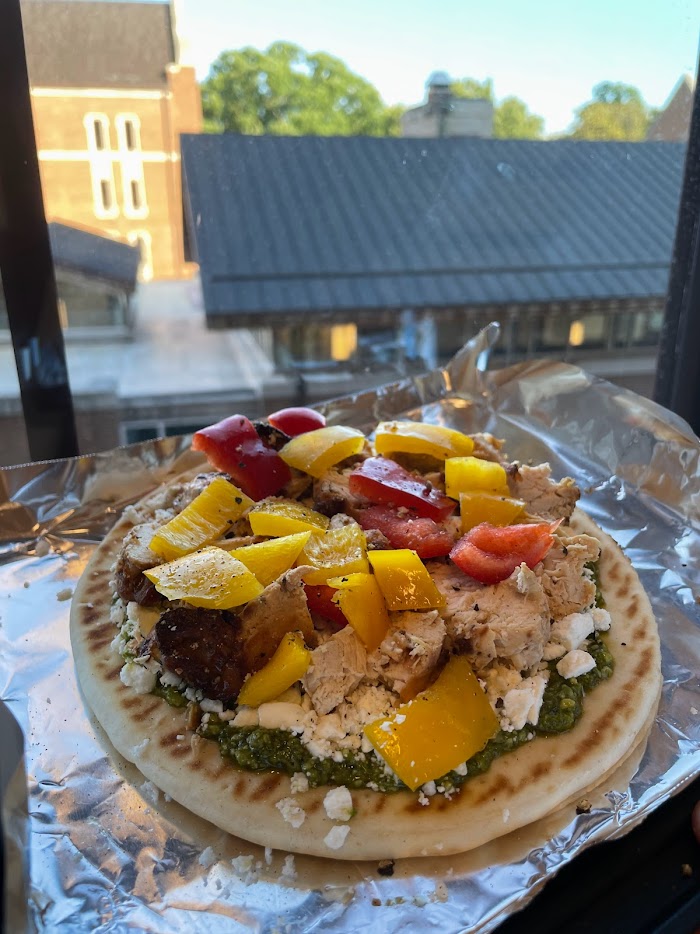
Chicken Pita Pizza
Time to be creative! I hadn’t had pizza in a while but saw the opportunity to make it after surveying all the ingredients in my dorm room. I used pita bread as the crust and feta for the cheese. It didn’t taste like a traditional pizza, but it sure looked like one. Rating: 7.5/10
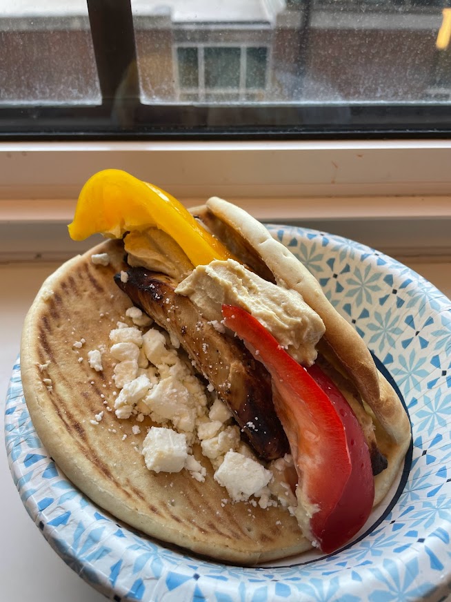
Chicken Gyros
The chicken was marinated in greek yogurt, which tenderized the meat and added a tangy flavor. With lots of ingredients and seasonings, the dish had depth, but the star of the show was the feta crumbles on top. Rating: 7/10
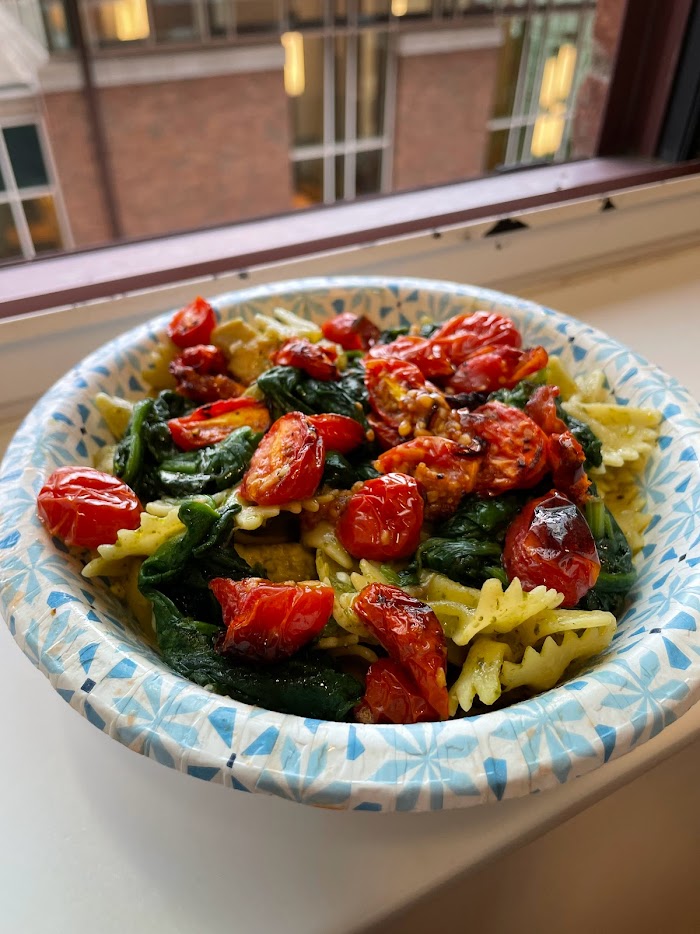
Chicken Pesto Pasta
I was craving pasta and needed to use up a jar of week-old pesto. The chicken turned out a little dryer than I like, but the overall flavor was solid. I decided to add spinach and roasted tomatoes with garlic for some veggies, which made the dish pop! Rating: 7/10
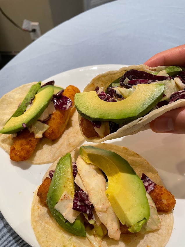
Crispy Fish Tacos w/ Homemade Coleslaw
I forgot to defrost chicken thighs, so I had to think of a quick protein source I could use for dinner. Crispy fish sticks did the job. I made a quick coleslaw with cabbage but decided to use Japanese mayo as it has a richer taste. The coleslaw was underwhelming but added a nice crunch to the soft taco. Rating: 7/10
Chicken Fajita Tacos
Just some classic chicken fajitas with corn tortillas. The chicken could have used more seasoning and was a little dry, but the guacamole on top helped. I ended up buying way too many corn tortillas than I needed for this dish! Rating: 6/10


 While the initial 3x3 array prototype allowed for better thermal detection and testing, the fragile circuitry on the bread board led to sporadic issues such as command signal delays that caused multiple TEM devices to overheat and melt. Because of such faults and concerns for the user’s safety, for the next month a graduate student and I started working on transitioning the thermal device to a 4x4 array controlled by a PCB. Safety hardware such as emergency shut off switches and software fail safes were also implemented. After weeks of redesigning mounts, building TEM devices, assembling hardware, and updating the control code to provide more thermal device features, a more robust 4x4 thermal array was developed.